By
John B. Cornwell, David W. Johnson, and William E. Martinsen
Presented At American Institute of Chemical Engineers 1990 Summer National Meeting San Diego, California August 19-22, 1990
Abstract
Pressure relief valves and vents in the petrochemical industry are often the last line of defense in averting a major accident. Recent design standards (API 520/521) have been developed which have reduced the recommended exit velocities for hydrocarbons from pressurized storage.
There are computer models available which predict the release and dispersion of high velocity gas jets. In some instances, these models have been modified to account for the formation and dispersion of aerosol clouds. This paper will compare the API recommended practices with actual test data and current model predictions.
Text

Pressure relief valves and vents in the petrochemical industry are often the last line of defense in averting a major accident. Recent design standards (API 520/521) have been developed which have reduced the recommended exit velocities for hydrocarbons from pressurized storage.
There are computer models available which predict the release and dispersion of high velocity gas jets. In some instances, these models have been modified to account for the formation and dispersion of aerosol clouds. This paper will compare the API recommended practices with actual test data and current model predictions.
Introduction
Within the hydrocarbon and chemical processing industries, the use of pressure relief devices to protect process equipment and storage tanks from excessive internal pressure is commonplace, and is often required by government or industry codes. In many cases, discharges from pressure relief devices flow through a closed piping system to an elevated vent or flare. One primary function of an elevated flare or vent is to safely dispose of flammable and/or toxic gases released by the pressure relief devices, either by burning the gas to create less hazardous products of combustion, or by releasing it at an elevation that is sufficient to ensure that hazardous concentrations of the gas will not return to grade level.
This type of system generally works well and is often the preferred method for disposing of hazardous gases released from pressure relief devices. However, such systems are not, and cannot be, used universally. There are many situations where it is not practical to connect pressure relief devices to a vent or flare header. For example, pressure safety valves (PSVs) on storage tanks for refrigerated liquefied gases relieve at low pressures, typically 2.0 psig or less. To safely dispose of this low pressure gas through an elevated flare or vent would require a very large diameter header system, otherwise the pressure drop in the header would create excessive backpressure on the relief valves. A similar argument applies to vent valves on API cone roof tanks.
In other cases, the available pressure may be sufficient for disposal through a vent or flare, but the mechanical configuration required to connect the relief device to a vent or flare system would be too expensive or too complex. This is the case for mobile tanks (e.g., tank trucks, railroad tank cars, and portable gas cylinders) and often applies to remote installations of storage tanks and small process units.
When it is impractical to have a pressure relief device discharge into a vent or flare system, the common alternative is to have the device discharge directly into the atmosphere. Normally, a short tailpipe or stack is connected to the outlet side of each pressure relief valve, oriented so that released gas is directed vertically upward. Some types of pressure relief devices, such as vent valves on API cone roof tanks, are not normally fitted with tailpipes and do not necessarily discharge vertically upward.
The release of flammable or toxic gas from a pressure relief device directly to the atmosphere raises an important safety question.
- Will the gas return to grade at a concentration great enough to be hazardous due to its flammability or toxicity?
The answer to this question is not a simple ‘yes’ or ‘no’ but depends on several factors related to the atmospheric dispersion of gases.
API RP-521 [American Petroleum Institute, 1982] addresses some of the safety issues related to the discharge of gases from relief devices directly to the atmosphere. Technical work sponsored by the API [Taylor, et al., 1951] indicated that high velocity (>500 ft/sec) releases of light hydrocarbons mix rapidly with air and will be diluted below their lower flammable limits within a distance equal to about 120 times the diameter of the discharge pipe (i.e., the flammable plume created by a vertical release of propane vapor from a 4-inch diameter pipe at a velocity of 500 ft/sec should not exceed 40 ft in length). The study concluded that the hazard of flammable concentrations existing below the point of discharge was negligible as long as the discharge velocity is high.
Over the years, skepticism arose concerning the validity of the previous investigation. One primary concern was the ability to maintain the high velocity under all relieving conditions. The high velocity might be achieved when the relief valve is flowing at its design capacity, but the valve might not close until the flow has been reduced to approximately 25% of its rated capacity. Thus, it is possible that the discharge velocity could be reduced to one-fourth of the desirable velocity.
An additional study [Hoehne, et al., 1970] was undertaken to evaluate the effects of reduced discharge velocities, temperature and molecular weight of the gas being discharged, and wind velocity. This study, and a similar study on releases from tank ship vents [ICS, 1978], indicated that a discharge velocity of 100 ft/sec was sufficient to prevent the flammable plume from dropping below the elevation of the discharge point.
It is important to note that these three studies apply only to vertical releases of flammable gases. If liquid is being discharged or the discharge stream includes liquid droplets as well as gas (i.e., an aerosol), meeting the discharge velocity criteria of 100 ft/sec may not be sufficient to ensure that the flammable plume will not drop below the discharge point. Similarly, a discharge velocity of 100 ft/sec may not create sufficient dilution of toxic gases.
Dispersion Methodology
In evaluating the hazards associated with releases of pressurized liquids or gases, methods must be employed that accurately predict the release conditions and subsequent dispersion of the material. There are several types of models available which may be used to calculate the dispersion of vapors into the atmosphere. Most of the available models are based upon theories developed in the 1940s to predict the dispersion of smokestack plumes from power plants. These models, referred to as Gaussian (after the pre-determined concentration profiles), do not take into account several important factors, (e.g., the temperature of the emitted gas, molecular weight, exit velocity, and any dilution effects except those of simple diffusion theory). In order to accurately model the dispersion of gas from pressurized liquid or gas releases, more complex models are required. These models must contain algorithms which account for thermodynamics, mixture behavior, two-phase fluid behavior, transient release rates, gas cloud density relative to air, release velocity, and heat transfer effects.
To model the gas/air plume created by a release of gas from a pressurized source, Quest Consultants Inc. uses a model originally developed by Ooms [1972]. This model is applicable for all molecular weight gases and has proven successful in predicting the shapes of plumes from both experimental and industrial flue stacks [Ooms, 1972].
Additional validation studies have been performed by the United States Coast Guard [Trainor, Parnarouskis, and Prosser, 1986; Astleford, Morrow, and Buckingham., 1983]. The Coast Guard carried out a series of over 100 experimental releases, measured the downwind distance the plumes traveled, and compared the results to the Ooms model predictions. Agreement between experimental data and model predictions was very good.
Case Studies
In order to demonstrate the dispersion behavior of gases under different release conditions, several example problems will be described. The releases vary from high velocity gas releases, to low velocity gas releases, to moderate velocity aerosol releases. The release scenarios can be characterized as:
- High velocity PSV release of LPG vapor.
- High velocity PSV release of ammonia vapor.
- Low velocity venting from a crude oil tank.
- Low velocity venting of ullage gas from a crude oil tanker.
- High velocity release of LPG liquid (aerosol) through a PSV.
In the cases described above, several different scenarios will be evaluated in order to provide a range of solutions to the question “how far and how fast?” As it is impossible to define the “worst case” atmospheric condition for any release/dispersion event, all the cases were evaluated under the same atmospheric conditions:
- Air temperature = 70°F
- Relative humidity = 75%
- Wind speed (@ 10 m) = 5 mph
- Pasquill-Gifford atmospheric stability class = D
Case 1: LPG PSV Venting
As described earlier, the atmospheric venting of hydrocarbons from pressurized storage is a common element in plant design. The recommendations in API RP-521 provide for the safe venting of flammable gases (i.e., the flammable plume does not come back to grade) if a minimum velocity of 100 ft/sec is maintained at the release point.
Case 1a:
In this example, liquefied petroleum gas (LPG) vapor is being released from a PSV with a rated capacity of 40,000 scfm. The PSV is located on top of the vessel with the tailpipe oriented vertically upward. The tailpipe has a cross-sectional area of 50 in2 and terminates 40 ft above grade. The composition of the LPG is:
- 95.5% propane
- 4.5% n-butane
which has an associated lower flammable limit (LFL) of 2.1 mole percent.
Using the momentum jet dispersion theory described earlier, the flammable plume will establish itself in the position shown in Figure 1 in less than ten seconds. From Figure 1, it is clear that the flammable plume (as described by 1/2 LFL) does not reach grade. (The choice of performing calculations to 1/2 LFL is often made to provide a safety factor in the analysis.) If it is assumed that the atmospheric conditions remain constant, the plume will neither increase nor decrease in size while the valve is relieving at the rated capacity.
Case 1b:
A second calculation was made for the same PSV just before the valve “reseats.” Since the rated flow rate in Case 1a was 40,000 scfm, the flow rate in Case 1b is 10,000 scfm. Under this condition of lower flow, the flammable plume will appear as in Figure 2. As in Case 1a, the flammable limit of the plume will not reach grade.
Case 1c:
An option often exercised in PSV design is to route the released gas to a flare so that it can be disposed of by burning it at a safe location. However, the situation is quite different if the flare is not burning when a PSV opens. If the release described in Case 1b is routed to an unignited flare with a stack tip 100 ft above grade and an exit diameter of 2 ft, the flammable plume will appear as in Figure 3. Under this set of conditions, the plume will start to slump (gravity settle) once out of the stack. This is primarily due to the gravity effects on the gas overcoming the velocity effects. The large diameter flare exit creates a low exit velocity, thus dropping the rate of air entrainment due to momentum effects. For most hydrocarbon systems, flare stacks are tall enough so that the flammable gases do not reach grade. However, each design of such interlocked systems must be carefully analyzed to ensure the proper dilution of gas below specified limits before the plume reaches grade.
Case 2: Ammonia PSV Venting
The hydrocarbon releases described in Cases 1a, 1b, and 1c are specifically covered in API RP-521. Questions often arise as to the applicability of RP-521 for toxic gas releases. In short, the application of RP-521 to toxic gases depends on the amount of dilution needed to eliminate the hazard due to the toxic gas effects. For hydrocarbon releases, a dilution ratio of 100 moles of air to 1 mole of gas will achieve the desired result of reducing the gas concentration below the LFL concentration (1 mole percent). This dilution, 100 fold, is easily achievable by maintaining high gas exit velocities. If a 100:1 dilution ratio were enough to bring a particular toxic gas/air mixture into safe concentration limits, the guidelines provided in RP-521 would be acceptable. However, most toxic materials require a much greater dilution rate in order for the gas/air mixture to be such that people can leave the area safely. As an example, Table 1 presents several common toxic materials and their Immediately Dangerous to Life and Health (IDLH) concentration values, as defined by the National Institute for Occupational Safety and Health (NIOSH).
Figure 1. Case 1a.
LPG PSV Release (285 PSIG)

Figure 2. Case 1b
LPG PSV Release (Low End Pressure)

Figure 3. Case 1c
LPG PSV Release To Flare

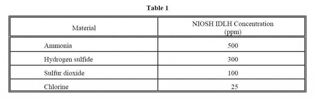
As can be seen in Table 1, much more dilution is necessary for the toxic material relative to the 100:1 ratio of air to gas necessary for the flammable hydrocarbon materials. For this reason, the ability to accurately describe the behavior of toxic gas releases is important in the design of PSVs.
In a scenario similar to Case 1, we have a pressurized ammonia storage tank with a 4000 scfm PSV located 10 feet above grade. The PSV tailpipe has an exit area of 12.5 in2 and is oriented vertically upward. For this example, the target concentration will be the IDLH value for ammonia, 500 ppm (i.e., 2,000:1 dilution ratio). As with the LPG vapor releases in Case 1, the exiting gas will be close to sonic velocity at the tip of the tailpipe. Figure 4 depicts the location of the cloud with a concentration of at least 500 ppm. This cloud geometry is reached in approximately 60 seconds and will remain in such a configuration until the pressure in the tank begins to drop (thus lowering the flow rate at the valve exit).
Figure 4. Case 2
Ammonia PSV Release (265 PSIG)

For ammonia vapor, the density of the gas/air plume will always be less than that of air. This allows for the plume to always be positively buoyant upon release. Thus, in instances where ammonia is released as a vapor, there is no slumping of the plume toward grade.
Case 3: Venting of a Crude Oil Tank
A second type of release, described in RP-521, is the low velocity release of hydrocarbon vapors from vents. This venting, or relieving, through low pressure vents presents a different set of exit conditions for evaluation. The low velocity releases do not entrain air at the high rate which the high pressure releases do and thus will not dilute to the 100:1 ratio nearly as fast (given the same mass flow rate). Under low pressure conditions, the chance of creating a slumping, slow moving vapor cloud is more likely.
Figure 5. Case 3a
Oil Field Battery Tank Vent

3a
Figure 5 presents the flammable plume evolving from a 2 psig vent located on top of an oil field battery tank. The vent has an exit area of 12.5 in2 and is oriented horizontally in the downwind direction. The lower flammable limit of the vapor is defined to be ~1 mole percent. As can be seen from Figure 5, the vapor immediately starts to slump toward grade upon release. The plume takes approximately 10 seconds to reach its full extent.
3b
If the vent were oriented vertically upward and all the previous conditions remained the same, the plume would look like Figure 6. With this release orientation, the flammable plume does not reach grade even though the gas velocity at the exit of the tailpipe is ~200 ft/sec.
Case 4: Crude Oil Loading Operation
Loading ocean-going crude oil tankers requires the venting of hydrocarbon/inert gas mixtures. In many instances, the hydrocarbon/inert gas mixture is released through a mast riser with one or more tips. Predicting the formation of the vapor cloud outside the mast riser is complicated by the time-dependent variations in composition and flow rate of the exiting gas. Composition of the exiting hydrocarbon/inert gas stream varies due to displacement of inert gas in the ullage space during loading. Flow rate out of the mast riser varies according to the loading rate of crude. As an example, Figure 7 is representative of a crude oil tanker loading rate versus time and Figure 8 is representative of the variable composition of the exiting gas as a function of time.
The following gas composition is taken from Figure 8.
- n-Butane = 6% n-Pentane = 2%
- i-Butane = 3% Ethane = 0.5%
- i-Pentane = 4% Methane = 0.25%
- Toluene = 3% C6+ = 2.5%
- Propane = 3% Inert gas (Co2, N2) = 75.75%
The lower flammable limit for this mixture would be approximately 1.7 mole percent. In this example, the mast riser is defined to be 45 feet above deck level and have an exit area of 7 ft2.
Figure 6. Case 3b.
Oil Field Battery Tank Vent (Verticle)

Figure 7
Crude Oil Loading Rate

Figure 8
Hydrocarbon Ullage Space Concentrations

Case 4a:
For a 40,000 bbl/hr loading rate, the ullage gas would be displaced at a rate of ~6 lb/sec. Figure 9 presents the location of the flammable plume released out of the mast riser. Under these conditions, the plume will start to slump slightly but will dilute below 1/2 LFL before reaching deck level.
Case 4b:
As the loading rate drops toward the end of the loading process, several things change in the analysis. First and most importantly, the exit velocity of the gas drops since the venting rate is proportional to the loading rate of crude oil. In addition, the hydrocarbon fraction of the released gas rises. The decrease in exit velocity, coupled with the higher hydrocarbon content of the gas, allows gravity to pull the plume down toward the deck. During this portion of the loading operation, it may be possible to encounter flammable gas at deck level. It is possible by the careful selection of mast riser exit areas (or multiple tip geometries) to force the gas to have a higher velocity at the exit point and thus retard the slumping of the gas/air mixture. An example of such a solution would be to put in a three-tip system with tips that could be remotely opened and closed to allow for greater exit velocities. If one of the three tips was open during the end of the loading process and the release area was 1/3 of the earlier single tip design, the exiting flammable plume would appear as in Figure 10.
Case 5: Liquified Gas Release through a PSV
Under unusual circumstances it is possible to force liquid through a PSV that is designed for relieving gases. If superheated liquid is forced through a PSV, a fraction of the liquid will instantly flash to vapor. Depending on the physical properties of the material and the amount of material flashed during depressurization, some or all of the unflashed liquid will be shattered into small droplets and entrained into the jettisoned gas. This vapor/liquid droplet mix, referred to as an aerosol cloud, behaves in some ways like the high velocity gas releases discussed above. Such parameters as rapid air entrainment due to momentum exchange, high travel velocities due to expansion of the fluid, and the initial resistance to the effects of the ambient wind field are all characteristics of the aerosol cloud. However, in many ways the aerosol cloud has characteristics
Figure 9 Case 4a
Crude Load Through Mass Riser

Figure 10 Case 4b
Crude Vapor Out of a 10 Inch Riser

which differentiate it from gas releases. Most importantly, the aerosol cloud is “carrying” with it a “source” of gas in the form of the liquid droplets. These liquid droplets (while adjusting to the equilibrium conditions in the cloud) slowly vaporize and produce additional gas which, in turn, must be diluted by additional entrainment of air. The thermodynamic process of reaching equilibrium and vaporizing the liquid forces the temperature of the gas/air/liquid mixture to drop. This increases the density of the mixture and increases the tendency of the cloud to gravity settle or slump to grade.
For example, assume the pressurized LPG bullet in Case 1 is overfilled and the PSV valve is opened, allowing liquid to exit the tank through the valve and flash upon depressurization to one atmosphere. The compositions of the various phase mass fractions are:
Table 1

The mass flow through the relief valve is controlled by the area available for liquid flow. For this example, it is assumed the exit area available for liquid flow through the valve is 4.8 in2. This produces a mass flow out of the PSV tailpipe of 175 lb/sec.
For the vertical release geometry described in Case 1a, the aerosol release defined above would yield a flammable cloud which is presented in Figure 11. As observed in Figure 11, the aerosol plume travels a greater distance in the flammable state and settles to grade while continuing to travel downwind.
Conclusions
Flammable gases can be safely discharged to the atmosphere if the guidelines presented in API RP-521 are followed (i.e., vertical release orientation with a velocity of 100 ft/sec or higher). Table 2 presents a summary of the dispersion results obtained in the paper. As can be seen from the comments in Table 3, the guidelines work well for most high velocity vertical hydrocarbon releases, while caution must be exercised when designing toxic gas relieving systems.
For releases of superheated flammable liquids or toxic gases, the combination of vertical release orientation and high exit velocity may not be sufficient to ensure that hazardous gas concentrations will not reach grade level. In such cases, additional safeguards will be necessary.
Figure 11. Case 5
LPG Aerosol Release Through PSV

References
- American Petroleum Institute (1982), RP-521 (Second Edition), Guide for Pressure-Relieving and Depressuring Systems. American Petroleum Institute, 1220 L Street, N.W., Washington, D.C., 1982.
- Astleford, W. J., T. B. Morrow, and J. C. Buckingham (1983), Hazardous Chemical Vapor Handbook for Marine Tank Vessels. Southwest Research Institute, San Antonio, Texas, April, 1983 (NTIS No. AD-A128 768).
- Hoehne, V. O., R. G. Luce, and L. W. Miga (1970), The Effect of Velocity, Temperature, and Gas Molecular Weight on Flammability Limits in Wind-Blown Jets of Hydrocarbon Gases. Report to the American Petroleum Institute, Battelle Memorial Institute, Columbus, Ohio, 1970.
- ICS (1978), International Safety Guide for Oil Tankers and Terminals. International Chamber of Shipping/Oil Companies International Marine Forum, Witherby and Company, London, 1978.
- Ooms, G. (1972), “A New Method for the Calculation of the Plume Path of Gases Emitted by a Stack.” Atmospheric Environment, Vol. 6, 1972: p. 899.
- Taylor, J. F., H. L. Grimmett, and E. C. Comings (1951), “Isothermal Free Jets of Air Mixing with Air.” Chemical Engineering Progress, Vol. 37, 1951: pp. 175-180.
- Trainor, R. H., M. C. Parnarouskis, and R. J. Prosser (1986), “The ONDEK Vapor Dispersion Model.” Proceedings of the 1986 Hazardous Material Spills Conference, May 5-8, 1986, St. Louis, Missouri: pp. 295-304.
Table 2
Summary of Dispersion Results

Table 3
Applicability of RP-521 for Releases Studied
